Technical Assignments |
||
In the first technical report of the Voorhees Replacement Hospital, the building is introduced through a brief explanation of function and a detailed description of the structural system including foundations, floor system, columns, lateral system, and the roof system. A list of the materials and governing building codes are also provided. Gravity loads are calculated using ASCE 7-05 and spot checks in typical bays are preformed. Wind and Seismic loads are also calculated using ASCE 7-05 and are compared to the structural engineer’s lateral loads. |
||
In the second technical report of the Voorhees Replacement Hospital, alternate floor systems are investigated. A typically interior bay of 29'-4" x 31-4" was analyzed and designed for four floor systems, including the existing, and were compared based on: weight, depth, vibration, fireproofing, constructability, lead time, cost, framing layout changes, and foundation changes. The existing floor system is composite steel and was chosen because of its light weight. The three other systems that are studied in this report include:
|
||
In the third technical report of the Voorhees Replacement Hospital, an in-depth analysis is performed on the building's lateral system. The existing lateral force-resisting systems consists of steel braced and moment frames in both directions. Calculations performed on the building consist of lateral force distribution, drift, torsion, overturning, and spot checks are completed on certain lateral members. An ETABS model is created in order to help with the above mentioned calculations. Only the lateral system is modeled in ETABS and values calculated by hand using ASCE 7-05 are applied to the model. |
||
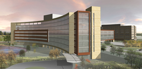 |
The Virtua Health
Replacement Facility |
Voorhees, New Jersey |
|
Paul R. Stewart |
|
Structural Option |